Updated:
TV Video PAL Signal Generator with Arduino
Before you can understand the code shown below you should first understand what is and what format a composite PAL video signal has. There are good sources of information about this topic, see References section.
Hardware
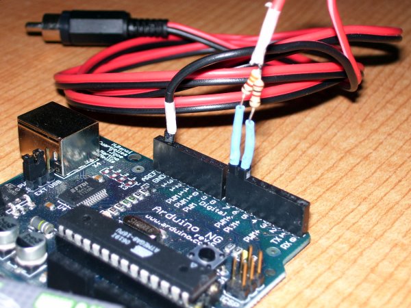
Apart from Arduino and a cable with male RCA connector, you need a DAC (Digital To Analog Converter) of 2-bits. It's very easy to construct simply with two resistors of 330 Ohm and 1 kOhm like the image below shows. The output voltages are:
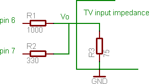
| Pin 7 | Pin 6 | Output Voltage | Level |
|---|---|---|---|
| 0 | 0 | 0.0 V | Sync level |
| 0 | 1 | 0.3 V | Black level |
| 1 | 0 | 0.6 V | Gray level |
| 1 | 1 | 1.0 V | White level |
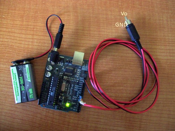
metal case is ground and the inner metal is Vo |
|
|
|
Software
An enhanced version of the following code was sent to me by Tobie Kerridge (thanks Tobie!). It uses inline assembler (nops) and ifs to achieve a more accurate timing.
      /*
      Vertical Bars Pattern PAL TV Signal Generator with Arduino
      Use this code as you want
      2007 Javier Valcarce Garcia, <javier.valcarce@gmail.com>
      */

      #include <avr/io.h>
      #include <util/delay.h>

      ///////////////////////////////////////////////////////////////////////////////////////
      // Pins where the 2-bit DAC is connected

      #define PINA0 6 // LSB, 1 kOhm resistor
      #define PINA1 7 // MSB, 330 Ohm resistor

      // PINA1 PINA0 OUTPUT
      // 0     0     0.0V   - Sync level
      // 0     1     0.3V   - Black level
      // 1     0     0.6V   - Gray level
      // 1     1     1.0V   - White level

      #define LEVEL_SYNC   PORTD &= ~(1 << PINA1); PORTD &= ~(1 << PINA0);
      #define LEVEL_BLACK  PORTD &= ~(1 << PINA1); PORTD |=   1 << PINA0;
      #define LEVEL_GRAY   PORTD |=   1 << PINA1;  PORTD &= ~(1 << PINA0);
      #define LEVEL_WHITE  PORTD |=   1 << PINA1;  PORTD |=   1 << PINA0;
      ///////////////////////////////////////////////////////////////////////////////////////

      ///////////////////////////////////////////////////////////////////////////////////////
      inline void vsync_pulse()
      {
      LEVEL_SYNC;
      _delay_us(30);
      LEVEL_BLACK;
      _delay_us(2);
      }

      ///////////////////////////////////////////////////////////////////////////////////////
      inline void equal_pulse()
      {
      LEVEL_SYNC;
      _delay_us(2);
      LEVEL_BLACK;
      _delay_us(30);
      }
      ///////////////////////////////////////////////////////////////////////////////////////
      inline void hsync_pulse()
      {
      LEVEL_SYNC;
      _delay_us(5); //4.7us
      LEVEL_BLACK;
      _delay_us(7); //7.3us
      }

      ///////////////////////////////////////////////////////////////////////////////////////
      int main()
      {
      register unsigned int line;

      /* NOTE THAT THE SIGNAL GENERATED BY THIS PROGRAM HAS A NOT VERY ACCURATE TIMING SO
      IT IS POSSIBLE THAT THE IMAGE BLINKS ON YOUR TV SCREEN OR DOESN'T SHOW AT ALL,
      THIS PROGRAM WRITTEN IN C (INSTEAD OF ASSEMBLER) IS ONLY A PROOF OF CONCEPT */

      line = 0;
      DDRD = 0xFF; // PORTD, all pins are outputs

      while(1)
      {

      if (line == 626)
      {
      line = 1;
      }
      else
      {
      line++;
      }


      switch(line)
      {
      case 1:
      case 2:
      case 314:
      case 315:
      vsync_pulse();
      vsync_pulse();
      break;

      case 3:
      vsync_pulse();
      equal_pulse();
      break;

      case 4:
      case 5:
      case 311:
      case 312:
      case 316:
      case 317:
      case 623:
      case 624:
      case 625:
      equal_pulse();
      equal_pulse();
      break;

      case 313:
      equal_pulse();
      vsync_pulse();
      break;
      default:
      // Image scanline (not a sync line)

      hsync_pulse(); // Horizontal Sync, lenght = 12us

      LEVEL_GRAY;
      _delay_us(8);
      LEVEL_BLACK;
      _delay_us(14);
      LEVEL_WHITE;
      _delay_us(8);
      LEVEL_BLACK;
      _delay_us(14);
      LEVEL_GRAY;
      _delay_us(8);
      //52us in total
      }
      }
      }
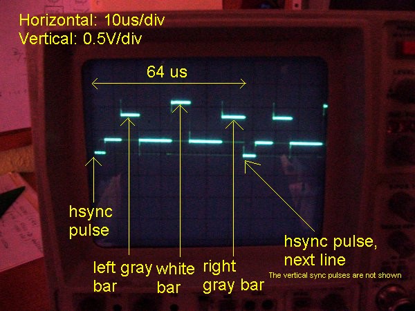
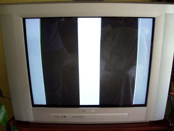
The generated signal timing is not very accurate so is possible that image flicks on screen tv. If you use a PC TV card instead a real TV be aware that this kind of receivers are very flexible about timing so in most cases they display the image perfectly. Try in a classical TV to assure yourself that it works.
Compile and upload
This software is written in pure C, not in Processing (the Arduino language) because in Processing is very difficult to control the time with accuracy. See Program Arduino with AVR-GCC for details of how to compile and upload C programs to Arduino.
More Gray Levels And Colour Images
In you want a deeper gray scale, then use a DAC with more resistors, see Binary-Weighted Digital To Analog Converter.
It's not possible to generate a colour composite signal with Arduino running @16MIPS unless you use separate RGB/Sync components video input of your TV, also known as SCART (Euroconnector). See this for more information.
If you want generate colour composite signals you must use a faster MCU like SX (up to 75MHz), see SX Game System for a great project about this topic.
Real Time Issues and Further Projects
TV image signal generator is an example of a very hard real-time task that is difficult to accomplish in software @16MIPS like in Arduino. It's for this reason that this task it is normally done in hardware. The clasical aproach in graphical video systems is:
- The image we want show on TV/VGA monitor/etc is stored in a memory zone called the "video buffer".
- An electronic circuit (VDG - Video Display Generator, like the classical MC6847) reads this video buffer and generates the video signal.
- Usually there are two video buffers, one is the "work buffer" in which we write the next frame graphics while the other is the "display buffer", in which the hardware is reading to generate video signal. These buffers interchange their roles with each new frame. This avoids screen blinking.
- In modern video cards there is also a CPU on board (GPU - Graphical Procesor Unit) that executes 2D primitives (bitblit, YUV scale, fill a region with color, etc) or 3D (triangle and projection calculus) very very fast on video memory.
- A software API like OpenGL or DirectX that communicates with board via operating system drivers and make the GPU to draw primitives, do effects, etc on video memory.
With Arduino @16MIPS is possible to generate in C simple static images directly as the electron beam sweeps the screen (there is no video buffer because there is not enough memory in Arduino). But, for a sequence of different and/or more complex images you should use assembly instead of C because you will need to count instruction cycles. Plan carefully your code organization and do tasks like general calcs taking avantage of constant colour zones into the TV line.
In general, for long delays, the use of hardware timers is much preferrable as they free the CPU and allow for concurrent processing of other events while the timer is running. However, in particular for very short delays, the overhead of setting up a hardware timer is too much compared to the overall delay time. In this cases you should use busy-wait delay loops that locks the CPU.
Good Luck!